lab07 : Simulation of Single-Cycle MIPS CPU
| num | ready? | description | assigned | due |
|---|---|---|---|---|
| lab07 | true | Simulation of Single-Cycle MIPS CPU | Fri 02/28 08:00AM | Sun 03/08 11:59PM |
Due Sunday, March 8th at 11:59 PM
Goals for This Lab
By the time you have completed this work, you should be able to utilize pyrtl and Python to simulate common single-cycle CPU hardware for multiple instructions.
Step by Step Instructions
In class, you have been learning about the datapath and how a single-cycle CPU works. Now, we will actually implement a single-cycle CPU using PyRTL!
Note: This lab will take SIGNIFICANTLY more time than the previous labs. Plan to spend more time on debugging too. It is your best interest NOT to start the assignment in your TAs’ office hours on Monday/Tuesday, but rather to start as early as possible and use office hours for debugging help! You are given a few extra days than usual to complete this lab, so use your time wisely and don’t leave things until the last minute!!
Task
Your task is to implement a single-cycle CPU using PyRTL that can run the following 9 MIPS instructions.
ADD, AND, ADDI, LUI, ORI, SLT, LW, SW, BEQ
Provided Files
We have provided you with 3 files, linked here:
-
cpu.py- This is a sample runner program. It contains information on how to test and debug your program. You should thoroughly read through this after you’ve implemented everything for this assignment. -
sample_test.s- This is a sample assembly program that you can use to test your CPU once it’s completed. -
i_mem_init.txt- This contains the assembled instructions fromsample_test.s, which will be loaded into the instruction memory of your CPU before the simulation begins.
Instructions
You may implement the CPU however you wish, but here is the suggested approach.
Design the CPU on Paper
You should reference the CPU diagram on page 265 (Figure 4.17) of your textbook (without jumps implemented). Think through which components, wires, and control signals you’ll need at a high level. Figure is reproduced here:
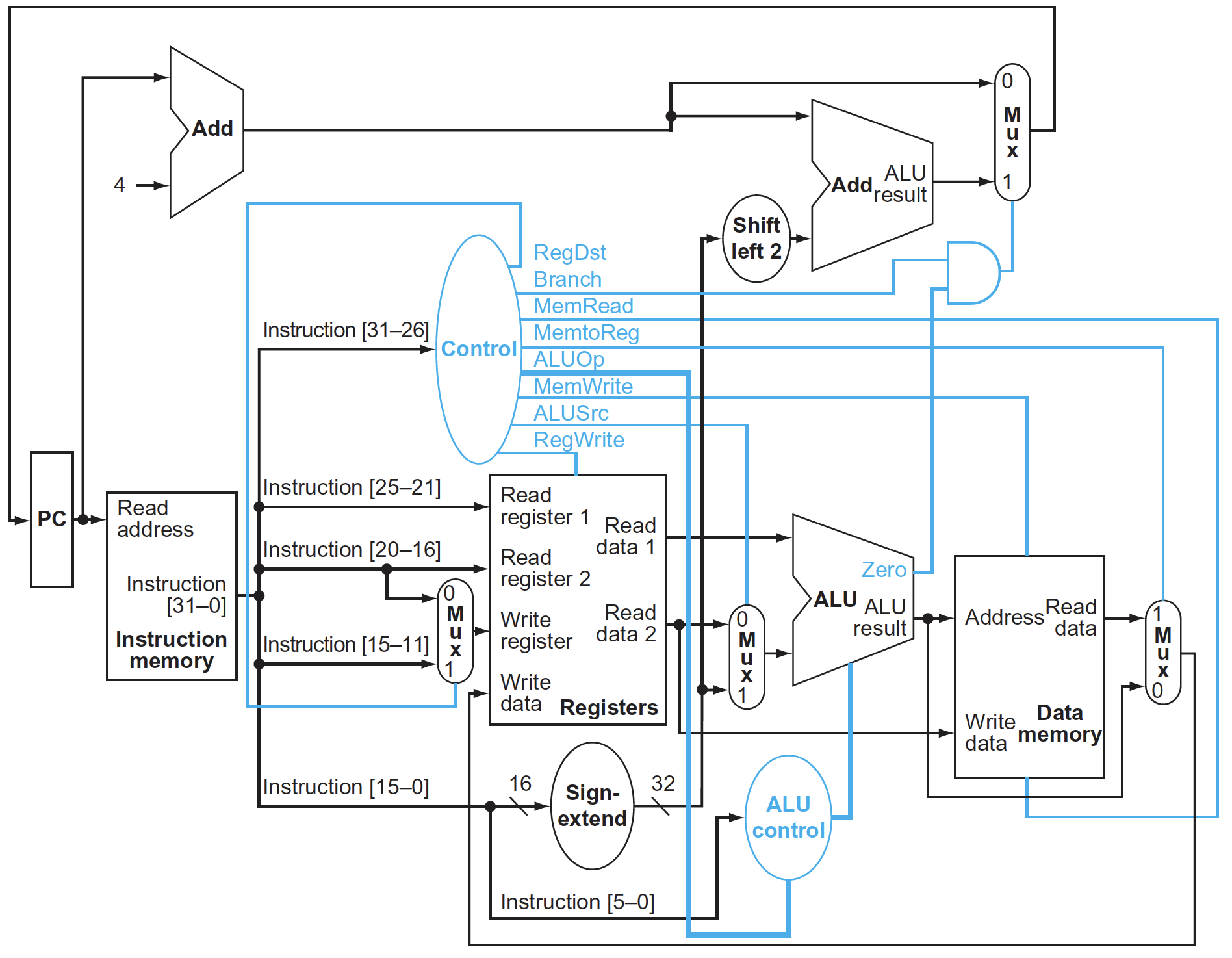
Hint: Your CPU will be almost identical to this one!
Compute Control Signals
You will need to implement a control unit for your CPU. To use an analogy from your textbook: the various components of your CPU are like an orchestra - you have several “players” like the register file, the memory, the different muxes, etc. However, the CPU needs someone to “conduct” these “players”. The controller is this “conductor”. The controller tells the different components when they’re needed to perform a task (like writing to memory), and when they should not. It accomplishes this by sending out “control signals” to each of the components.
Depending on the instruction, the controller asserts certain control signals as “on” and others as “off”. It’s your job to figure out which ones are needed for which instruction! To make this easier for you, we’ve made a spreadsheet available here.
For each column, simply enter a “1” if that instruction needs the control signal asserted, or a “0” otherwise. If the value doesn’t matter, you can enter either “0” or “1”.
For the 3-bit ALU_OP column, enter any number you want in the range of [0, 8). This number tells the ALU what it should do with its inputs - add them, shift them, etc. Since you are creating the ALU, you are free to choose whatever ALU_OP values you want for each operation, as long as you are consistent.
We have filled out the control signals for the “ADD” instruction as an example. We assigned an ALU_OP of 0 for addition. Other instructions that also need to add values together in the ALU would use the same ALU_OP of 0.
Finally, there is a column called “CONCATENATED”. This column takes the bits from all 9 signals and concatenates them together for you automatically. It then displays the number in hex. You can use this hex value in your PyRTL code if you wish.
Build and Connect your Hardware Modules
From the previous 3 PyRTL labs, you should have a good idea of how to implement an instruction decoder, an ALU, a register file, and memory. Do the same thing here! Take the CPU you designed on paper and implement it in cpu.py.
Hint: You will need 3 memories in your code.
i_mem: stores your instructions.d_mem: stores your data.rf: stores your register values.
Test your Design!
You’ve implemented your CPU in PyRTL, but have no idea whether it’s right. How do you test it? Well, we just need to write some sample MIPS programs and run them on your CPU! If the programs work without any problems, then your CPU is probably correct. How do you do that?
- Write a MIPS program.
- Assemble the MIPS program.
- Copy and paste the assembled instructions (machine code) in hex format into
i_mem_init.txt python cpu.py
We’ve provided you with a sample test case in sample_test.s. The assembled test can be found in i_mem_init.txt. More information about how to test is provided in the skeleton cpu.py; please read through these files carefully so you can understand how to test and debug your code.
Submission
Requirements
To test your code, we require the following 3 things:
- Your instruction memory variable must be a MemBlock called
i_memand should be available from the top level. - Your data memory variable must be a MemBlock called
d_memand should be available from the top level. - Your register file variable must be a MemBlock called
rfand should be available from the top level.
If you can run the following from the same directory as your cpu.py file, then you are probably good to go.
(venv) $ python -c 'import cpu; cpu.i_mem; cpu.d_mem; cpu.rf; print("Good to Go!")'
Good to Go!
Files to Submit
The only thing you need to submit for this lab is the file cpu.py. We will have a GradeScope submission available by the weekend. Please keep your eyes open for any Piazza announcements in case we make updates to the submission requirements.
Autograder
Unlike previous labs, we will NOT be releasing an autograder to verify your solutions. Part of this assignment is to learn how to test your code! What we WILL allow you do instead is share test code (MIPS assembly) with each other on Piazza. While this is completely optional, you may write your own comprehensive test suite in MIPS and share the program on Piazza under our stickied post, and you may also download your classmates’ tests if they’ve uploaded them. We (the instructors) will not be responsible for debugging any mistakes in these test suites, nor will we endorse any of them. If you think there is a bug or issue with a test suite, you should comment under the author’s submission with your concerns. Lastly, passing these tests is not a guarantee of any score on the assignment or from the autograder.
Hints
Your TAs have already implemented a solution and made a list of things that might be useful to know for this assignment!
- The control unit is actually pretty simple. It’s a 1:1 mapping of
op/funcfrom the instruction to a set of control bits. The easiest way to implement this is with a Mux (pyrtl.conditional_assignment).
Example:
control_signals = pyrtl.WireVector(bitwidth=9, name='control_signals')
with pyrtl.conditional_assignment:
    with op == 0:
        with func == 0x20:
            control_signals |= 0x280
        ...

# Extract the relevant signals
alu_op = control_signals[0:3]
...
-
In your textbook, there is a “MemRead” control signal. This is not required in our CPU.
-
You will probably run into errors unless you add
asynchronous=Trueinto your pyrtl MemBlock declarations ford_memandrf. -
You will need a WRITE ENABLE on the
d_memand register filerf. -
Some control signal values don’t matter. You can set them to either 0 or 1 since they don’t matter. For example: BEQ’s REG_DST doesn’t matter. It can be either 0 or 1 since we’re not writing to the register file anyway during BEQ instructions.
-
No writes should happen to the zero register. It should always read 0.
-
In your test MIPS programs, you should end with a branch back to the same instruction forever. You don’t know exactly how many cycles the simulation will run, and we do not have a “halt” instruction, so to smoothly exit you should just keep looping forever when you’re done with your business logic.
-
When using
pyrtl.corecircuits.shift_left_logical, you cannot pass a constant as the second argument unless you use aConst.
Example:
shift_left_logical(some_wire_vector, 2) # BAD!
shift_left_logical(some_wire_vector, Const(2)) # GOOD!
-
Remember to sign extend your immediate values!! You will run into some very hard to debug errors with your branching if you don’t do this! You can do this with the
.sign_extended()function on WireVectors. -
Watch out for ORI! It is an I-Type instruction that uses a zero-extended immediate value instead of a sign-extended value.